Flex & Rigid/Flex Solutions
Engineered Solutions » Flex & Rigid/Flex Solutions
- POLYIMIDE FLEX CIRCUITS, CABLES AND HEATERS
Polyimide flex circuits, cables, and heaters designed and manufactured by Fralock are critical components for major OEM’s in technically advanced markets. We provide high-precision single and multi-layer fine-pitch flex and rigid-flex circuits where applications require interconnections in a compact package. Our All-Polyimide flex solutions are smaller, lighter, and can seamlessly integrate into almost any form you need.
High-Reliability Flex Circuit and Heater Manufacturer
Fralock builds flex circuits and heaters to your exact specifications with predictable performance. High-reliability rigid-flex circuits, which combines a flex circuit with a rigid conductor such as a connector or a circuit board, can be found in applications ranging from medical devices to aircraft guidance systems. With a low profile, compact outline, bendable capability, and low weight, Fralock flex and rigid-flex circuits are commonly used in a wide variety of industries.
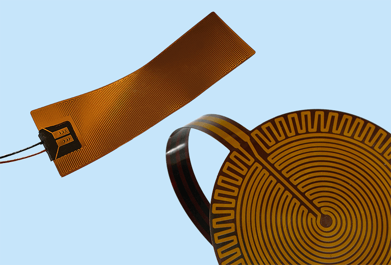
Our flexible heaters feature etched metal tracings between two sheets or strips of polyimide material. These thermofoil heaters are ideal for applications that require complex shapes and contours, as well as those with tight space and weight constraints.
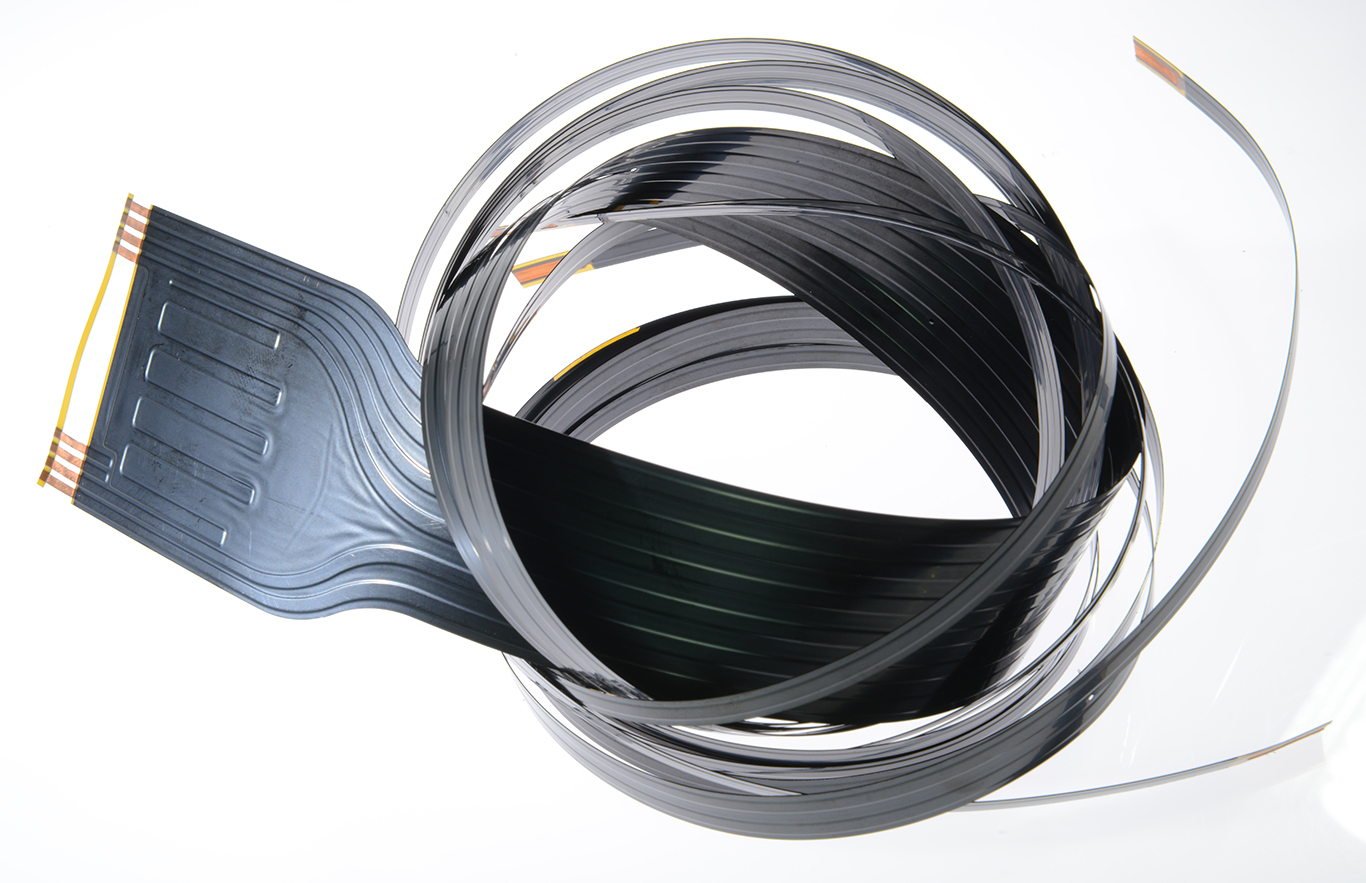
Fralock’s etched foil cables can be folded without affecting performance. Our capabilities include production of flex circuits and heaters without any adhesives, using our Adhesiveless Lamination Technology (ALT)™. Eliminating the need for adhesives also enables tolerance to a wider range of temperatures, from -269° to 250° Celsius (-452° to 478° Fahrenheit) and renders them about 30 percent thinner and lighter, saving space and labor costs. ALT Dura™ flex products are flex circuits and heaters made using ALT technology.
Our flex circuit manufacturer services include consignment, quick-turn, prototyping, production, and complete turnkey builds.
Frequently Asked Questions
The flexible circuit has just recently come of age as an interconnection device, although it was originally developed about fifty years ago.
Designers of applications from car stereos and cameras to heart pacemakers and disk drives, have all reaped the benefits of flex circuits. More applications are being discovered every day.
The flexible circuit was originally designed as a replacement for bulky wire harnesses. Simple circuit designs helped to solve space and weight problems that could not be resolved using traditional wiring methods.
As technology advanced in leaps and bounds, new products required more compact packaging, minutely defined electrical impedances, and error-free product performance. Flexible circuitry gave the package engineer ways to miniaturize circuits, increase functional capacity, and improve reliability.
In addition to being flexible, flex circuits can be designed to meet highly complex special con figurations, and hostile operating environments are easily withstood by flex.
New products demand savings in space and weight with greater reliability. Because of these demands, the twenty-year-old technology of flexible circuits has come of age.
A basic flexible circuit is made of a flexible polymer film laminated to a thin sheet of copper that is etched to produce a circuit pattern.
Patterns can be created on both sides of the film. Interconnections are achieved with plated through-holes, yielding an almost unlimited adaptability between various component parts. A polymer overcoat is often added to insulate and environmentally seal the circuit.
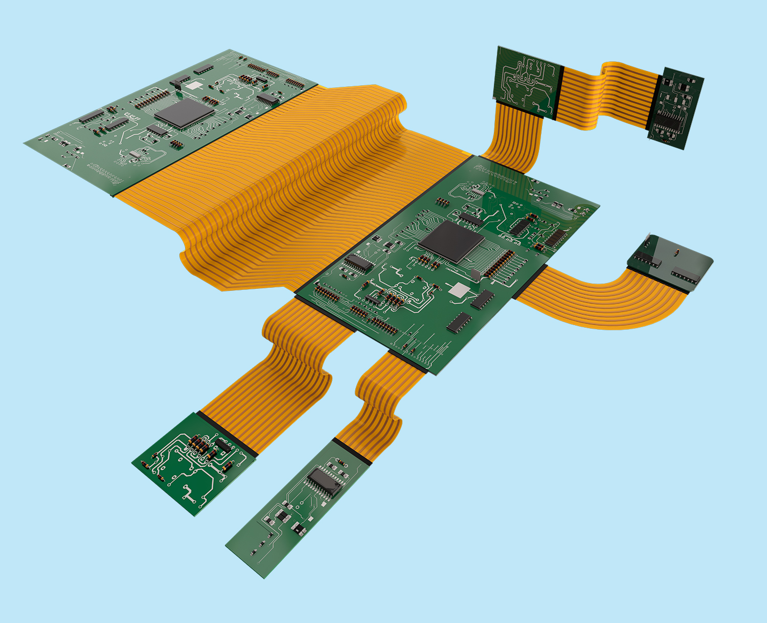
Flexible circuits can also combine several single- or double-sided circuits with complex interconnections, shielding, and surface mounted devices in a multi-layer design. These multi-layer designs can also be combined with rigid circuit boards to create a rigid-flex circuit capable of supporting devices as needed.
The most widely used polyimide film is DuPontTM KAPTON®, because of its high heat resistance, dimensional stability, dielectric strength, and flexural capability. The characteristics of this raw material help the flex circuit maintain a high degree of durability and help it survive hostile environments.
One thing that flexible circuits and rigid printed circuit boards have in common is that they both allow repeatable connections. Conductor routings in a flexible circuit are determined just like a rigid PC board by a single artwork, rather than by individual wirings.
Flexible circuits also allow extra-fine lines, as low as 2 mils on 4-mil centers, allowing high -density device population and reduced circuit size and weight.
But flexible circuits have one important advantage over rigid PC boards in that they give designers a third dimension with which to work. Flexible circuits can bend and shape around two or more planes during installation. They can solve space and weight problems by replacing several bulky boards with a single thin one. While in use, flexible circuits can also bend and flex up to 500 million times without a failure. This is something a rigid PC board simply cannot do.
Flexible circuits provide several benefits over rigid PC boards.
- Design Freedom – The most immediate benefit that flexible circuits give a package designer is an almost unlimited degree of design freedom.
- Flex circuits can fit in tight spaces. They can bend, fold, twist, change in width many times and even flex from a rolled configuration. This gives the package designer the freedom to relocate other parts and subassemblies where they will optimize circuit and equipment operation. The designer is no longer restricted by the space demands of bulky, rigid PC boards.
- Simplifying circuit geometry and placing surface mount devices directly on the circuit can also improve the circuit design. Intricate patterns that may be difficult to achieve with rigid board connector pins can be designed into the flexible circuit artwork. Greater circuit complexity is achieved in a much smaller space.
- Space and Weight Savings – Because flexible circuits can be configured to suit the contour of the equipment, designers can enjoy a space savings of up to 75%.
- The larger surface-to-volume ratio of flexible circuits also allows increased heat dissipation and lighter current capacity. Denser device populations and lighter conductors can be designed into a product, freeing space for additional product features.
- Even used as a flat circuit, flex saves space. The typical hard board is 62 mils thick, while a flex circuit is a mere 4 to 11 mils.
- The different raw materials used in flex also offer a weight savings as high as 70% versus the rigid board.
- High Reliability and Durability – Flexible circuits are made from precise replicas of artwork for superior manufacturing repeatability. The etched circuits replace the solder and hand wiring connections of the rigid board, completely eliminating wiring errors.
- The durability of the KAPTON polyimide survives vibration and shock that would damage a rigid board. KAPTON also provides increased thermal conductivity, providing an ideal thermal path to a heat sink. In designs that have moving parts, the flexible circuit can move and flex up to 500 million times without a failure. The exceptional thermal stability of KAPTON also allows the circuit to withstand applications with extreme heat.
- Cost Savings in Production – Production of designs using flexible circuits requires less manual labor and reduces the probability of production errors. The use of flexible circuits eliminates the high cost of routing, wrapping, and soldering wires.
- Complete interconnection systems are installed or replaced, rather than individual hard PC boards. This greatly eliminates wiring errors and reduces manufacturing costs. This automation also reduces the chance of human error and increases reliability in the design.
- Low volume applications benefit the most when circuit designs are very complex. Most high-volume applications get lower production costs regardless of the complexity of the circuit. In addition, as simpler, more direct methods of integrating circuits are discovered, the cost savings realized by flex increases. The use of conductive ink, anisotropic adhesives, and additive circuitry are ideal in designs using flex.
Advances in surface mount technology, mounting devices directly on circuits, have led to exceptional space and cost savings. Kapton’s excellent thermal stability provides a better base for surface mounting than hard boards. Because the compliant base film places less stress on soldered joints, thermal mismatch is less likely to occur.
With conductive adhesives, surface mount chips can be mounted on double-sided flex circuits. This eliminates the problem of soldering one device on a hard board, then soldering again on the other side, disturbing the previous connection.
Tape automated bonding (TAB) is another space-saving technology for which flex is ideal. Because KAPTON film can be etched so accurately, windows can be placed on the flex circuit to hold devices. The devices can then he soldered into place with TAB.
Rigid/flex combinations are perhaps the fastest growing flexible circuit designs. These hybrids combine the best features of rigid boards with the design flexibility of flexible circuits. These rigid/flex boards provide a higher component density and improved quality control. Designs can be rigid where support for components is needed, and flex around corners and in areas requiring extra space.
Another new flex circuit technology is called Bend/flex. Made of a copper-clad glass-polyester epoxy laminate, Bend/flex is a kind of flexible circuit that bends once to form to designs yet maintains its rigidity. Bend/flex can support electronic components without stiffeners and can allow auto-insertion of components before bending into its final shape.
Available in thicknesses of 15, 20, and 30 mils, Bend/flex can be drilled, blanked, plated, pierced, and wave soldered on one or both sides. It can replace mother/daughter board combinations or even rigid/flex combinations in some designs.
Advancements in the design of application-specific integrated circuits (ASIC) have helped flex become commonplace in many consumer electronics like cameras, computers, and home entertainment.
The benefits of flexible circuits are realized in most every application requiring high volume or high degree of accuracy.
In high volume applications, highly automated fabrication methods reduce human handling of the circuits, reducing both cost and probability of error. Applications like cameras, printers, disk drives, and automotive panels all benefit from high volume flex efficiency.
High accuracy circuits for aerospace and medical applications benefit from the flex circuit’s ability to handle ultra-fine lines and tight tolerances in an age of miniaturization.
Flexible circuits have been incorporated into several industries throughout the years including:
- Telecommunications equipment, telephone handsets, and switching systems
- Industrial controls, machine tool controls, and robotics
- Jet engines, navigational and flight control systems
- Heart pacemakers, hearing aids, and other medical applications
- Automotive radios, cassette players, electronic control systems and on-board computers
- Personal and mainframe computers, disk drives, and printers
- Consumer electronics like calculators, stereos, and cameras
There are three basic types of flexible circuits, varying in degrees of complexity. These three types of circuits can be used in different combinations to solve most every interconnection design problem.
- The simplest circuits are single-sided flexible circuits. They provide maximum flexibility for dynamic applications and can withstand hundreds of millions of flex cycles. These simple circuits are also the most easily adaptable to SMT, TAB, and other developments in circuit technology.
- Double-sided circuits are somewhat limited in their capacity to flex because of a thicker, more complex level of design. The ability to interconnect between sides using through-hole plating helps double-sided circuits carry complex designs, and still maintain flexibility.
- Multilayer circuits are ideal for complex, highly populated design requirements. Large numbers of conductors can be designed into a small package. Flexibility may be somewhat limited, depending on the number of layers in the design. These multi-layer circuits are ideal for rigid/flex designs, combining a multilayer flex circuit with a hard board.
Multilayer circuits are the ideal problem-solving technology when confronted with design challenges like unavoidable crossovers, specific impedance requirements, elimination of crosstalk in sensitive circuits, additional shielding or ground planes, and high component density.
In designing a flexible circuit, it is essential to consult a flexible circuit expert early in the design process. Flexible circuit manufacturers are not just production lines. They are manufacturing consultants and experts in the field of flexible circuitry.
Before beginning your flex design, examine your product requirements thoroughly. Know all the electrical requirements, dimensional restrictions, and assembly limitations. Consult flex circuit design guides throughout the design process to take full advantage of design trade-offs and improvements.
Start designing your flex circuit early, preferably as you start the design of your product. There are many variables in the design of a flex circuit. Conductor spacing, component addressing, designing for bend areas, and covercoat configuration and shielding must all be determined before your first prototype is produced.
By contacting a flex specialist early in the design process, you can get qualified design assistance, and be sure all design factors have been considered. A flex specialist can also check designs for manufacturability and even suggest design improvements for cost savings and improved performance. A prototype of the circuit should be built as soon as possible to allow time for design improvements. A prototype also helps your flex specialist further evaluate his ability to produce the design for you. At Fralock, we can rush these prototypes to you in as fast as 24 hours.
Remember that the flexible circuit manufacturer is essentially a design and manufacturing ser vice organization. Although flexible circuitry is different than hard board designs, it is not difficult to design and manufacture if you have the proper assistance.
The best way to become acquainted with a flexible circuit manufacturer is to take a tour of their facilities. Evaluate their experience and production capabilities and bring them in early in the design process to take full advantage of their flex expertise.
A flex circuit expert can find the best cost and performance value with a total systems approach.
At the conceptual stage, they can determine if your design is particularly suited for flex circuits. At a later stage they can evaluate and reevaluate designs as they progress, assisting with connector selection, fabrication techniques, assembly procedures and prototype testing.
If your design and prototype is completed early in your design process, it also allows your vendor adequate time to develop schedule and quotations for artwork, tooling, and production. This helps the flex circuit manufacturer serve you better with quality, low-cost circuits, and on -time delivery.
Your U.S. flexible circuit expert is Fralock. Our team of flexible circuit specialists can provide you the design and production assistance described in the preceding pages.
Whether you require a simple, single-sided flex circuit or a high-density, complex design, Fralock can solve your design problems with high-quality products made just for you.
If you want to learn even more about flexible circuits and what they can do for your product designs, call Fralock at 800-372-5625
- Adhesiveless construction resulting in more rugged, thinner, lighter and more flexible circuits
- Higher density circuits: trace and space capabilities from 3 to 5 mil (depends on part size and other factors)
- Microvia sizes down to .002″ diameter for high density, 2-layer flex circuits
- Selective plating of gold and tin leads enables multiple attachment methods on the same All-Polyimide flex circuits
- Alternate circuit layer materials such as beryllium, copper, stainless steel, and nickel can be used for optimum performance in unique applications
- Leaded and Lead-Free Assemblies
Applications include:
- Compact assemblies where electrical connections are required in 3 axes (static application)
- In space-constrained applications that prohibit the use of thicker circuit boards or wire harnesses
- Electrical connections where the assembly is required to flex during its use (dynamic application)
- Weight-sensitive applications such as hand-held devices, aircraft, or spacecraft where they replace heavier and bulkier wire harnesses
- High-performance applications where heat or insulation requirements preclude typical insulation materials
- Single-Sided Flex Circuits (single or multiple access)
- Double-Sided Flex Circuits
- Multi-Layer Flex Circuits
- Rigid-Flex Circuits
- Extended Length Flex Circuits
- Full Turnkey Assemblies
- Trace / Space 3 to 5 mil
- Micro / Vias Min 50u (2 mil) 2:1 aspect ratio
- Blind/Buried Vias (2mil) 2:1 aspect ratio
- Via Fill (conductive and non-conductive)
- Laser- Precision Drilling / Excising<50um (2mil)
- Layer Count Capability 1-10+
- Unsupported Traces / Cantilever Leads
- Controlled Impedance Routing Capabilities
- Surface Mount Technology (SMT) and thru-hole assembly services.
- Gold Plating (ENIG and Hard Gold)
- Liquid Soldermask Thickness 38um (1.5mil)
- Photo Imageable Coverlay Min 38um (1.5mil)
- RoHS & Non RoHS PCB/Flex Circuit Manufacturing
- Automated Optical Inspection (3D AOI)
- X-Ray, CT Scan
- Electrical Testing (Flying Probe, Functional Test , and Hi-Pot)
- Single-Sided Flex Circuits (single or multiple access)
- Double-Sided Flex Circuits
- Multi-Layer Flex Circuits
- Rigid-Flex Circuits
- Trace / Space 37um (1.5 mil)
- Micro / Vias Min 50u (2 mil)
- Blind/Buried Vias (2mil)
- Laser- Precision Drilling / Excising<50um (2mil)
- Layer Count Capability 1-10+
- Unsupported Traces / Cantilever Leads
- Controlled Impedance Routing Capabilities
- Liquid Soldermask Thickness 25um (1mil)
- Photo Imageable Coverlay Min 25um (1mil)
- RoHS & Non RoHS PCB/Flex Circuit Manufacturing
- Automated Optical Inspection (AOI)
- Electrical Testing (Flying Probe, Function, and Hi-Pot)
- Ability to Test for 10-15 Resistance Leakage
Our flexible and Rigid Flex PB meets IPC-6013: Qualification and Performance Specification for Flexible/Rigid-Flexible Printed Boards
- UL Certified
- J-Standard Certified
We provide flex circuit solutions in industries such as Aerospace/Defense, Medical, Semiconductor, Industrial, Electronics, and Energy.